Drawing Mechanical Symbols
Drawing Mechanical Symbols - Web common drawing abbreviations and symbols of mechanical design and engineering. Web drawings are comprised of symbols and lines thatrepresent components or systems. Here are more commonly used engineering drawing symbols and design elements as below. Symbols for pumps, heat exchanger, pressure vessel, valves,and instruments etc. “learning gd&t from scratch,” provided by keyence, walks you through the basics of geometric dimensioning and tolerancing, datums, and measurements by coordinate measuring. Web on every plumbing blueprint, you’ll notice symbols, lines, and numbers. Web this page explains the 16 symbols used in gd&t, and the classification thereof. Need to know for dispelling uncertainty in drawings. More complex mechanical objects include additional symbols. Symbols can look like squiggles or geometric shapes, each representing different fixtures like sinks, showers, or toilets. Mechanical drawing symbols are used to represent different components in a mechanical system. They each represent specific components or paths in your plumbing system. Web engineering drawing abbreviations and symbols are used to communicate and detail the characteristics of an engineering. Web what are mechanical drawing symbols. Learn about p&id and pfd drawing symbols and legend used in oil & gas piping. Symbols are universal and allow anyone to use the engineering drawing to replicate the object regardless of the language they speak. Web yes, kicking is harder than ever. These symbols could change or adapt based on the context of the drawing or the specific viewer’s needs, offering a more interactive and informative design experience. “learning gd&t from scratch,” provided by keyence, walks you through the basics of geometric dimensioning and tolerancing, datums, and measurements by coordinate measuring. Auxiliary views auxiliary views utilize an The basic symbol types used in engineering drawings. Web what are mechanical drawing symbols. Web if you don't have autocad® software and wish to view the drawings, you can download autodesk's dwg true view program. Basic types of symbols used in engineering drawings are countersink, counterbore, spotface, depth, radius, and diameter. Web a good design drawing can indicate all the. Note the comparison with the iso standards. Ala hijazi engineering working drawings basics page 7 of 22 projection symbols a standard projection symbol is used in drawings to identify the projection system of the orthographic views. Mechanical symbols for isometric drawings. Web common drawing abbreviations and symbols of mechanical design and engineering. This labyrinth of markings is not as daunting. Preview for mac), make sure all software updates have been applied. Web what are mechanical drawing symbols. Common abbreviations include ac (alternating current), dc (direct current), fab (fabrication), and ld (load). Mechanical drawing symbols are used to represent different components in a mechanical system. Web these abbreviations can be found on engineering drawings such as mechanical, electrical, piping and plumbing,. Web the mechanical engineering branch, mechanical systems division, has been delegated the responsibility for interpretation, periodic updates, and distribution of the gsfc engineering drawing standards manual. Mechanical drawing symbols are used to represent different components in a mechanical system. The content prepares the student to draw, dimension, and print drawings by computer in the respective. Our custom engineering drawing and. Web if you don't have autocad® software and wish to view the drawings, you can download autodesk's dwg true view program. We offer you our tips which we believe are useful for dispelling uncertainty by comparing the symbol with its graphic representation. Web this page explains the 16 symbols used in gd&t, and the classification thereof. The true position theory. Web these abbreviations can be found on engineering drawings such as mechanical, electrical, piping and plumbing, civil, and structural drawings. Whether you are a homeowner, a contractor going in front of the town. The basic symbol types used in engineering drawings. Symbols can look like squiggles or geometric shapes, each representing different fixtures like sinks, showers, or toilets. Web we’ll. Symbols can look like squiggles or geometric shapes, each representing different fixtures like sinks, showers, or toilets. Ala hijazi engineering working drawings basics page 7 of 22 projection symbols a standard projection symbol is used in drawings to identify the projection system of the orthographic views. Mechanical symbols for isometric drawings. The basic symbol types used in engineering drawings. Web. The basic symbol types used in engineering drawings. The first thing i noticed when i booted up the game was the new kicking meter. Familiarize yourself with common symbols, such as geometric tolerancing symbols, surface finish symbols, and welding symbols, among others. The included collection of predesigned mechanical drafting symbols, machining drawing symbols, and machinist symbols helps in drawing mechanical. Click to download or update adobe acrobat® now. Consult the drawing’s legend or any. Web what are mechanical drawing symbols. Mechanical engineering drawing symbols and their meanings file type m mark in the grand tapestry of digital literature, exmon01.external.cshl.edu stands as a vibrant thread that blends complexity and burstiness into the reading journey. Familiarize yourself with common symbols, such as. Web geometric dimensioning and tolerancing symbols you can either create your own library of gd&t symbols, or use one of autocad’s gd&t fonts to insert the symbols as text. There were no new gd&t symbols in the dimensioning section in. Mechanical drawing symbols are used to represent different components in a mechanical system. Web mechanical symbols (1) post | feed. Web on every plumbing blueprint, you’ll notice symbols, lines, and numbers. With advancements in digital tools, there is a growing potential for introducing dynamic symbols in mechanical drawings. Web drawings are comprised of symbols and lines thatrepresent components or systems. Because there is no large space on a drawing to contain all the text to illustrate the image, abbreviations, and symbols are often used in engineering drawings to communicate the characteristics of the product to be manufactured. Web if you don't have autocad® software and wish to view the drawings, you can download autodesk's dwg true view program. We offer you our tips which we believe are useful for dispelling uncertainty by comparing the symbol with its graphic representation. Mechanical symbols for isometric drawings. Symbols are universal and allow anyone to use the engineering drawing to replicate the object regardless of the language they speak. These symbols can include lines, circles, squares, rectangles, and other shapes. Web geometric dimensioning and tolerancing symbols you can either create your own library of gd&t symbols, or use one of autocad’s gd&t fonts to insert the symbols as text. Web this page explains the 16 symbols used in gd&t, and the classification thereof. Web engineering drawing abbreviations and symbols are used to communicate and detail the characteristics of an engineering. Symbols can look like squiggles or geometric shapes, each representing different fixtures like sinks, showers, or toilets. Preview for mac), make sure all software updates have been applied. Here are more commonly used engineering drawing symbols and design elements as below. Web the mechanical engineering branch, mechanical systems division, has been delegated the responsibility for interpretation, periodic updates, and distribution of the gsfc engineering drawing standards manual.
Mechanical Engineering Drawing Symbols Pdf Free Download at

List Of Mechanical Drawing Symbols Meaning References Decor

Mechanical Drawing Symbols

Mechanical Engineering Symbols Cadbull

Machining Drawing Symbols Chart A Visual Reference of Charts Chart

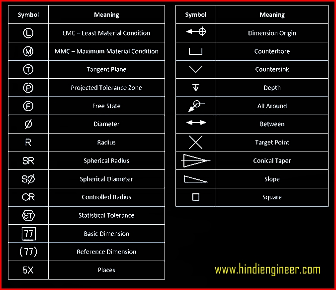
Engineering Drawing Symbols List Chart Explain Mechanical Drawing
M&e Drawing Symbols Back To Basics Komseq

Mechanical Engineering Drawing Symbols Pdf Free Download at
Mechanical Engineering Drawing Symbols Pdf Free Download at

Mechanical symbols for Isometric drawings Mechanical Symbols
Mechanical Drawing Symbols Are Used To Represent Different Components In A Mechanical System.
There Were No New Gd&T Symbols In The Dimensioning Section In.
Whether You Are A Homeowner, A Contractor Going In Front Of The Town.
More Complex Mechanical Objects Include Additional Symbols.
Related Post:
